

Category
Recommended Products
CI503P COLOR ANALYZER
CI550 COLOR ANALYZER
CL138 UV light meter
CI510 COLOR ANALYZER
CL503 illuminance colorimeter
CI300 Color Analyzer
CL300 illuminance colorimeter
CI820 SPECTRAL LUMINANCE COLORIMETER
CL320 UV Meter
CI350 LUMINANCE COLORIMETER
Contact Us
E-mail:info@huicolor.com
Tel:0086 755 2317 9385
Mobile:0086 135 0006 9487
Technical Articles
Communication between HUICOLOR colorimeters and PC, and instructions for secondary software of colorimeters
- Time:2026-07-21
- Visits:1
I Communication Overview
1.1 Communication Instructions
The physical interface method for communication between colorimeters (HUICOLOR) and PC computer: serial port (USB to virtual serial port, win10 or win11 computer driver free) or BLE Bluetooth.
Communication protocol: Modbus RTU protocol based on serial port, default device address for colorimeters is 1.
Through USB hub extension, up to 255 colorimeters can be tested synchronously, following the corresponding C # development demo.
High-end colorimeters can test over 80 photometric and chromatic parameters. PC computers can read corresponding register addresses and parameter data, with flexible and adaptable configurations. Read instructions and register addresses refer to the corresponding technical documentation.
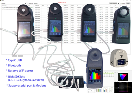
Figure 1
1.2 Communication Process
After connecting the colorimeters to the PC computer, the process of sending test instructions from the PC to the instrument is shown in Figure 2:
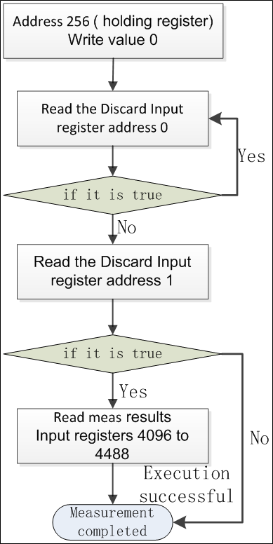
figure 2
After connecting the colorimeters to the PC computer, the PC sends the process of reading records of instrument as shown in Figure 3:
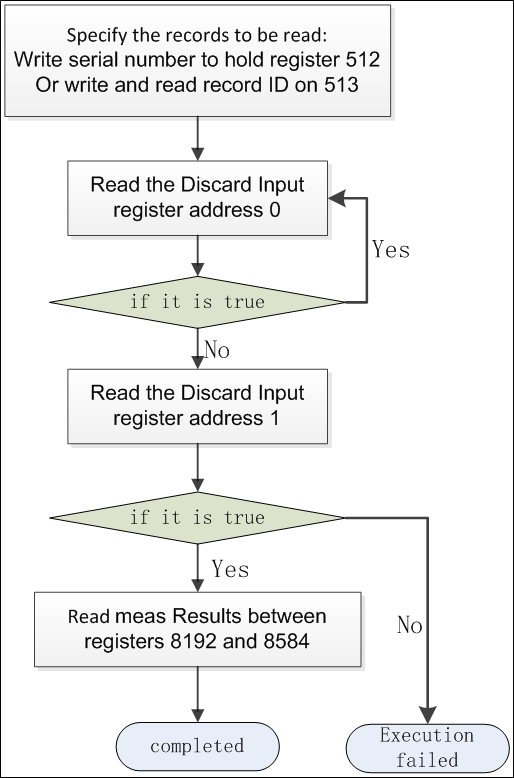
figure 3
1.3 Communication parameter description
Due to the fact that the values of all registers are directly read from the instrument data, which is stored on a small end basis, all register values need to be swapped byte order first, then converted into byte arrays and assembled according to the corresponding types.
Data type description:
A. Float: Single precision floating-point number, 4 bytes, stored in two registers;
B. Int32:signed 32-bit integer, 4 bytes, stored in two registers;
C. Uint32: unsigned 32-bit integer, 4 bytes, stored in two registers;
D. Int16: signed 16 bit integer, 2 bytes, stored in one register;
E. UInt16: unsigned 16 bit integer, 2 bytes, stored in one register;
F. Bytes [N]: byte array, each register stores two bytes;
G. Bool: storage type, one bit
The values in the register list of the document " Modbus Registers Description-CL,CI colorimeters-EN.xlsx " are not valid for all models of instruments. For example, in instruments that support the 400-700nm spectral range, radiation spectrum data below 400nm and above 700nm are invalid values. For specific data that is valid, please refer to the parameters supported in the instrument specification sheet.
Please refer to the example program (C # DEMO) for specific conversion instructions.
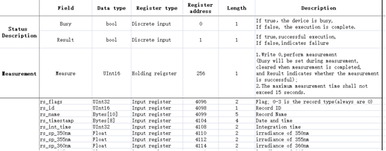
figure 4
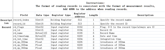
figure 5
II Command Description
2.1 Modbus Command Description
Note: Except for the storage address and length of Modbus, all other structured data is in small end mode.
2.2 Reading Instrument Status
- Type: Discrete input;
- Address: 0x0000;
- Quantity:`8`bites;
Status bit description:
- `status[0]`: busy bit,1:busy,0:ready;
- `status[1]`: Result indication, 1 indicates successful, 0 indicates failed execution;
- `status[2:7]`: reserved;
Note: Operations such as meas. and deleting records will not be completed immediately, and it is necessary to read the status to see if the results have been executed.
2.3 Obtaining Instrument Information
- Type: input register;
- Address: 0x0000;
- Quantity:` sizeof(struct DeviceInfo_t)`byte ;
struct DeviceInfo_t {
char model_name[20]; // Instrument model
char sn[10]; // serial number
char software_version[20]; // software version
char hardware_version[20]; // hardware version
uint16_t product_id; // Product ID
char probe_number[12]; // Header ID
};
2.4 Setting Instrument Time
- Type: holding register;
- Address: 0x0000;
- Quantity:`3`half world,Must be entered simultaneously;
struct Time_t {
uint8_t year;
uint8_t month;
uint8_t day;
uint8_t hour;
uint8_t minute;
uint8_t second;
};
2.5 Measurement
- Type: holding register;
- Address: 0x0100;
- Quantity:1,
Measurement type, '0' indicates automatic, values greater than zero indicate integration time, in units of 'ms'.
The measurement is relatively slow. You can check whether the measurement is completed by traversing the status bit. When the status changes to ready and the result is OK, you can read the measurement result.
2.6 Reading measurement results
- Type: input register;
- Address: 0x1000;
- Quantity: 256.
Data structure reference Record_t .
.......
III Utilizing QModBus Assistant to Quickly Communicate with colorimeters
Note: This document is only used as an example to illustrate and demonstrate the feasibility of relevant technical solutions. All software mentioned in the document does not provide any unauthorized installation packages. Please be sure to obtain genuine software through legal and compliant channels such as the official website of the corresponding product or authorized agents.
3.1 Software Description
QModBus is a general-purpose software similar to the serial assistant.
The essence of QModBus RTU is still serial communication, which is similar to serial communication.
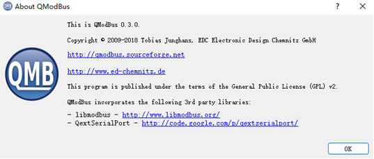
figure 6
3.2 QModBus and Colorimeters Communication Instructions
This article presents the process of communication between QModBus-0.3.0 and the instrument.
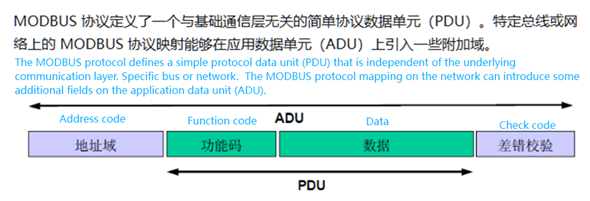
figure 7
3.2.1 Software installation, double-click to open after installation.

figure 8
3.2.2 The instrument is connected to PC via TypeC cable (Bluetooth is also possible) (Windows 10 or above computers come with built-in drivers).
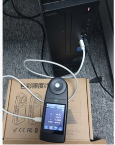
figure 9
3.2.3 Open QModBus to set communication parameters, as shown in the following figure.
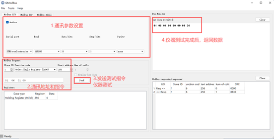
figure 10
3.2.4 As shown in Figure 9, QModBus send a test command, the instrument receives the test command, and measure, and returns the result data after the test is completed.
3.2.5 As shown in Figure 10, QModBus send the command to read the illuminance, and the instrument returns the illuminance data.
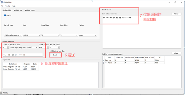
figure 11
3.2.8 As shown in Figure 11, QModBus send the command to read color temperature, and the instrument returns color temperature data.
3.2.9 Users can send corresponding read commands for any parameters they need, and the instrument will return the corresponding data.
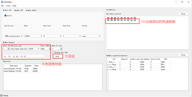
figure 12
3.2.10 According to the definition instructions in the file " Modbus Registers Description-CL,CI colorimeters-EN.xlsx ", the received hexadecimal data is parsed to obtain the corresponding illuminance and color temperature data in decimal format.
IV Secondary Development of Colorimeters on PC Computers
Note: This document is only used as an example to illustrate and demonstrate the feasibility of relevant technical solutions. All software mentioned in the document does not provide any unauthorized installation packages. Please be sure to obtain genuine software through legal and compliant channels such as the official website of the corresponding product or authorized agents.
4.1 Secondary development of C++platform
The libmodbus driver library is a Modbus driver library implemented in C language, which can be deployed on MFC. The Qt platform can use the QModbusRtuSerialServer class to build serial servers, which can be used to establish communication between PC and instruments, and develop applications that are suitable for oneself.
The upper computer software HIQC is developed using the QT platform.
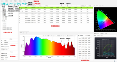
figure 13
4.2 Secondary Development of C #
The implementation of Modbus communication in C # is mainly accomplished through the NModbus library, which is used to build communication between PC and instruments. Refer to the routine DEMO to quickly achieve synchronous testing of multiple instruments.
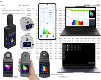
figure 14
4.3 Secondary development of LabView
The implementation of Modbus communication in LabVIEW is mainly accomplished through the NI Modbus Libaray library, which is used to build communication between PC computers and instruments. Referring to the routine DEMO, rapid testing can be achieved.
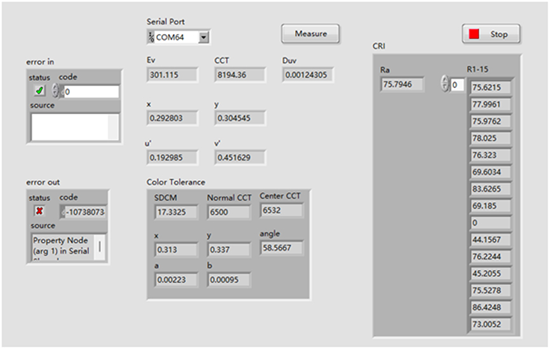
figure 15